VEX V5 Speedbot
Project documentation identifies the base as a Speedbot V5 with a V5 brain, two smart drive motors, wheels, and metal structural parts. I treated the assembled platform as the hardware layer for the programming and sensing tasks.
 Aiden YeungENGINEERING × FINANCE
MAIN JUNIOR-YEAR PROJECT / GRADE 11 / SPRING 2026
I programmed a VEX V5 robotic car to move through timed driving tasks, recognize colors, and follow a blue tape path. My main work was the VEXcode Python control logic: testing it on the floor, finding why it failed, and revising the sensor and steering behavior until it completed the documented route.
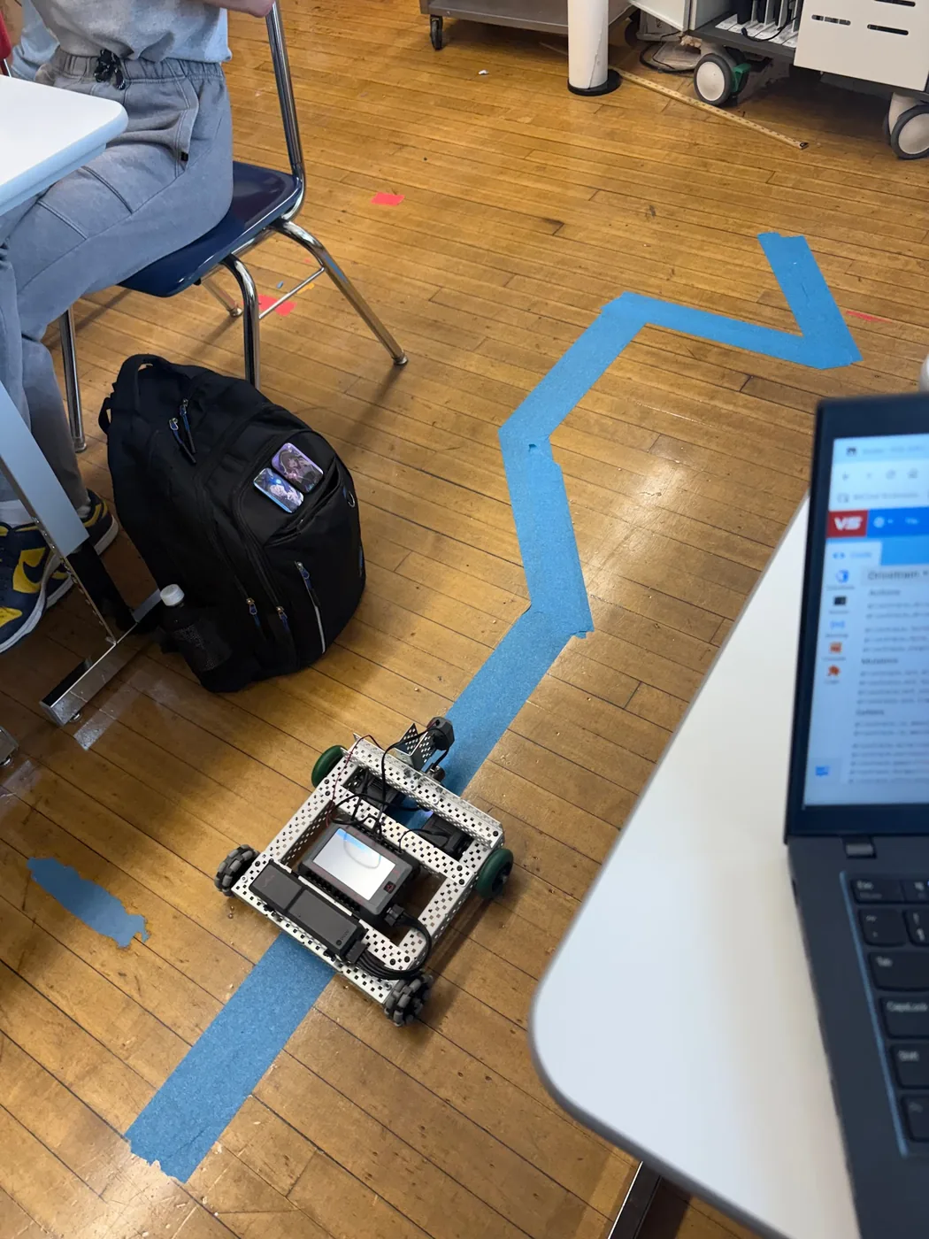 FIG. 01 / FLOOR TRIAL
Project focus This page documents my programming, sensor, and debugging work on the VEX V5 Speedbot platform.
APRIL — MAY 202601 / OBJECTIVE & SYSTEM
The work progressed from basic motor commands to sensor-guided behavior. The central challenge was connecting code to what the robot actually sensed and did on the floor.
Project documentation identifies the base as a Speedbot V5 with a V5 brain, two smart drive motors, wheels, and metal structural parts. I treated the assembled platform as the hardware layer for the programming and sensing tasks.
I wrote the initial forward command and later code for timed motion challenges, color detection and counting, blue-line following, and AI Vision sensor configuration. I tested behavior on the floor and adjusted the program when its output did not match the intended movement.
A sensor only becomes useful when its readings lead to a clear action. I had to decide what counted as “on the line,” how the robot should correct when the signal disappeared, and how it could search without turning away permanently.
02 / DEVELOPMENT LOG
Project work documented from April 17 to May 22, 2026. The programming moved through increasingly complex tasks, with each round of testing exposing a new failure mode.
I wrote a basic Python command to drive forward and began using the V5 drivetrain in code. Early tests raised practical questions about motor direction, wiring, battery placement, and how the brain was mounted.
I rewrote the motor configuration after the car moved in the wrong direction, then coded four route challenges using forward and reverse commands, timed movement, and right turns. The project record documents 5.51-second drive intervals and turns of 180°, 270°, and 360°.
I moved from drivetrain-only behavior to sensor input: detecting a target hue, identifying recognized colors, and counting red, blue, green, and yellow readings in a timed interval. I enabled the sensor light and tested the logic with colored paper.
I used a hue range for blue tape and adjusted the motor speeds and steering corrections. The first revisions could follow some of the course, but turning, recovery, motor behavior, and the starting position still caused failures.
I added a start search, a remembered search direction, and a wider pivot routine for when the sensor lost the tape. The documented result shows the robot crossing to the end of the blue tape and reversing back to the start.
I configured the sensor and got its view to appear on the computer after an earlier display issue. The final entry describes the sensor as connected and visible; coding it into the existing autonomous routine was still the next step.
03 / PROGRAM DESIGN
I built up the behavior in stages: basic drive commands, optical color logic, and a line-following routine with a search state.
The first program simply commanded forward motion. When the robot moved backward or the wheel response did not match the command, I checked the motor direction setup and re-tested. Timed sequences were useful for early route exercises, though time alone does not guarantee a precise distance.
drivetrain.drive(FORWARD)

# Timed challenge pattern
# drive → wait → turn → drive
wait(5.51, SECONDS)
drivetrain.turn_for(RIGHT, 180, DEGREES)
Documented code history: initial forward command, later REVERSE/FORWARD corrections, and 5.51-second challenge intervals.
For the color activity, I enabled the optical sensor’s light, checked the returned color, and added a loop that counted recognized colors for ten seconds. I also added a short wait between readings so the loop could repeatedly check the sensor instead of relying on a single sample.
optical_6.set_light_power(100)
optical_6.set_light(LedState.ON)

while timer.time(SECONDS) < 10:
    current_color = optical_6.color()
    if current_color != last_color:
        count_color(current_color)
        last_color = current_color
    wait(0.1, SECONDS)
Simplified excerpt of the documented color-counting approach; helper setup and display output omitted.
The final documented approach uses hue readings to classify the blue line. When the line is visible, both motors drive at a low base speed. If the hue falls outside the blue range, the program makes a small correction in the last known direction; after repeated misses, it stops briefly and pivots to search the last known direction before sweeping the other way.
This is a simple feedback controller: it reacts to the most recent sensor reading rather than following a pre-programmed path. The search routine matters because the robot can momentarily lose the tape at a turn.
BLUE_MIN = 140
BLUE_MAX = 220
BASE_SPEED = 8
SEARCH_SPEED = 15
SEARCH_TURN_SPEED = 22
LOST_LIMIT = 2

on_line = BLUE_MIN <= optical_6.hue() <= BLUE_MAX
if on_line:
    drive_at(BASE_SPEED)
else:
    lost_counter += 1
    correct_or_search(last_direction)
The excerpt summarizes the documented logic; the full VEX API motor calls and recovery loops are simplified for readability.
04 / DEBUGGING & ITERATION
Project documentation captures hardware and software issues side by side. I learned to treat a bad run as a signal to isolate the cause, change one variable, and run another trial.
The first forward command did not produce forward travel. I revised the motor direction setup and checked the result on the floor before moving on to timed route code.
The notes describe uneven wheel tightness, a front wheel that sometimes would not roll correctly, and a motor that did not turn as expected. These issues could make sound code look wrong because the hardware response was inconsistent.
Early closed-loop work produced an “undefined variable” error. Another day, a previous code section was missing from the working record and had to be rebuilt. Keeping the sensor setup, constants, and helpers together became part of reliable iteration.
The optical sensor did not always stop at the expected color, and the readings needed to be measured on the actual test surface. I used hue thresholds for the blue tape and left room to adjust them after testing.
Some versions could not make turns reliably or turned in the wrong direction after missing the tape. I added a remembered direction, a short correction stage, and a stronger search if the sensor stayed off the line.
One successful early run began with the robot already on the line, which did not match the intended start condition. I changed the logic to search forward until it found the tape before entering the follow state.
My debugging pattern Observe the mismatch, separate sensor/code/hardware possibilities, adjust one setting, then repeat the floor test. The documented iterations show this most clearly in the successive blue-line programs from May 14 through May 19.
05 / DOCUMENTED RESULTS
These are documented milestones, not lab-grade performance measurements. Lap times, sensor accuracy, and repeated-run reliability were not recorded.
Four challenge routines were recorded after the direction logic was revised.
APRIL 27The optical sensor loop counted red, blue, green, and yellow readings over a timed interval.
MAY 8The final line-following code used this hue range as its blue-tape detection threshold.
SENSOR SETTINGThe May 19 entry records a full traverse to the end of the blue tape and a return to the beginning.
MAY 1906 / DOCUMENTED VISUAL ARCHIVE
Selected project photographs show the platform, the color and tape test setups, and the sensor-configuration work.
FIG. 02 / BLUE TAPE COURSE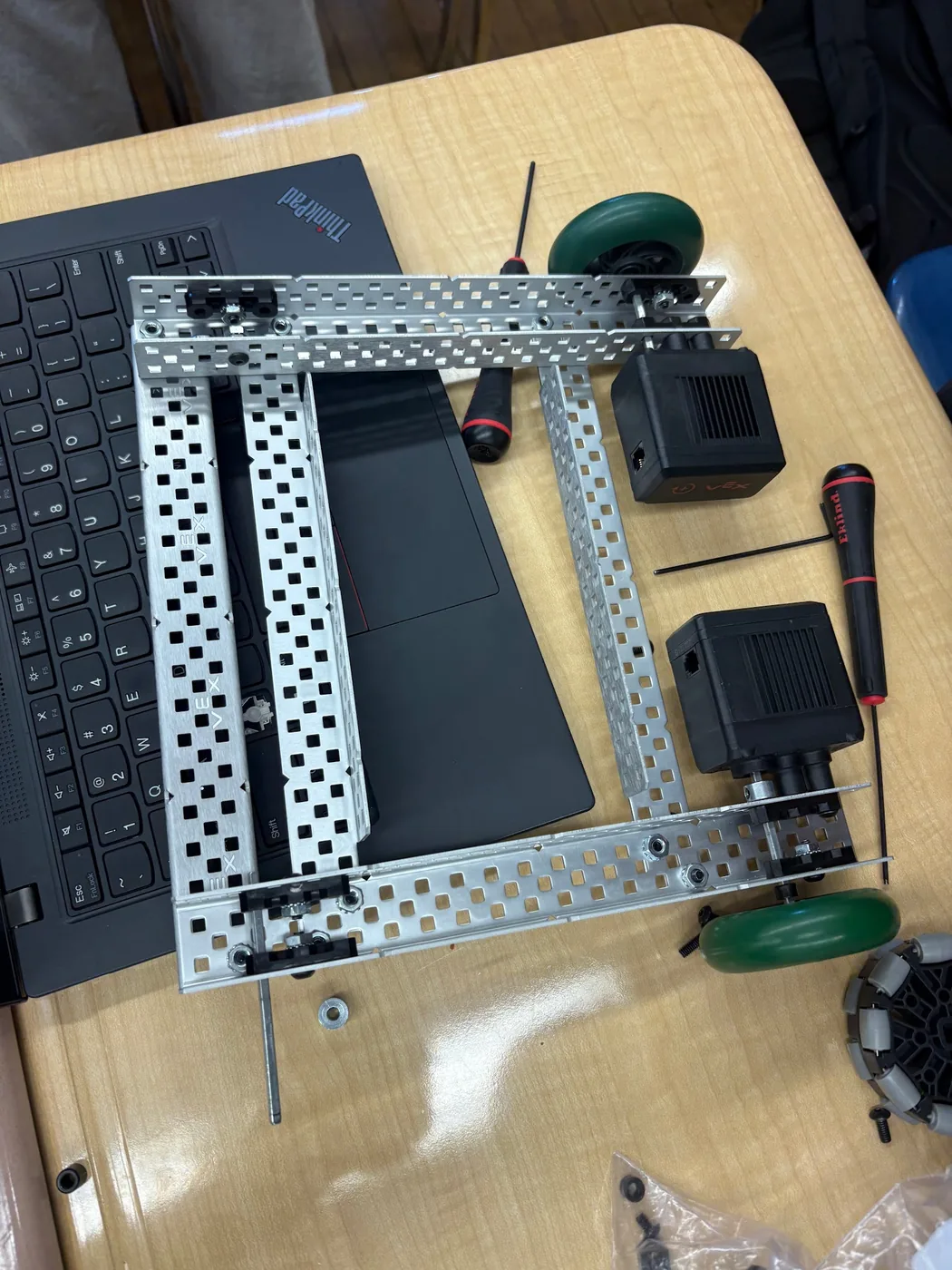 FIG. 03 / PLATFORM
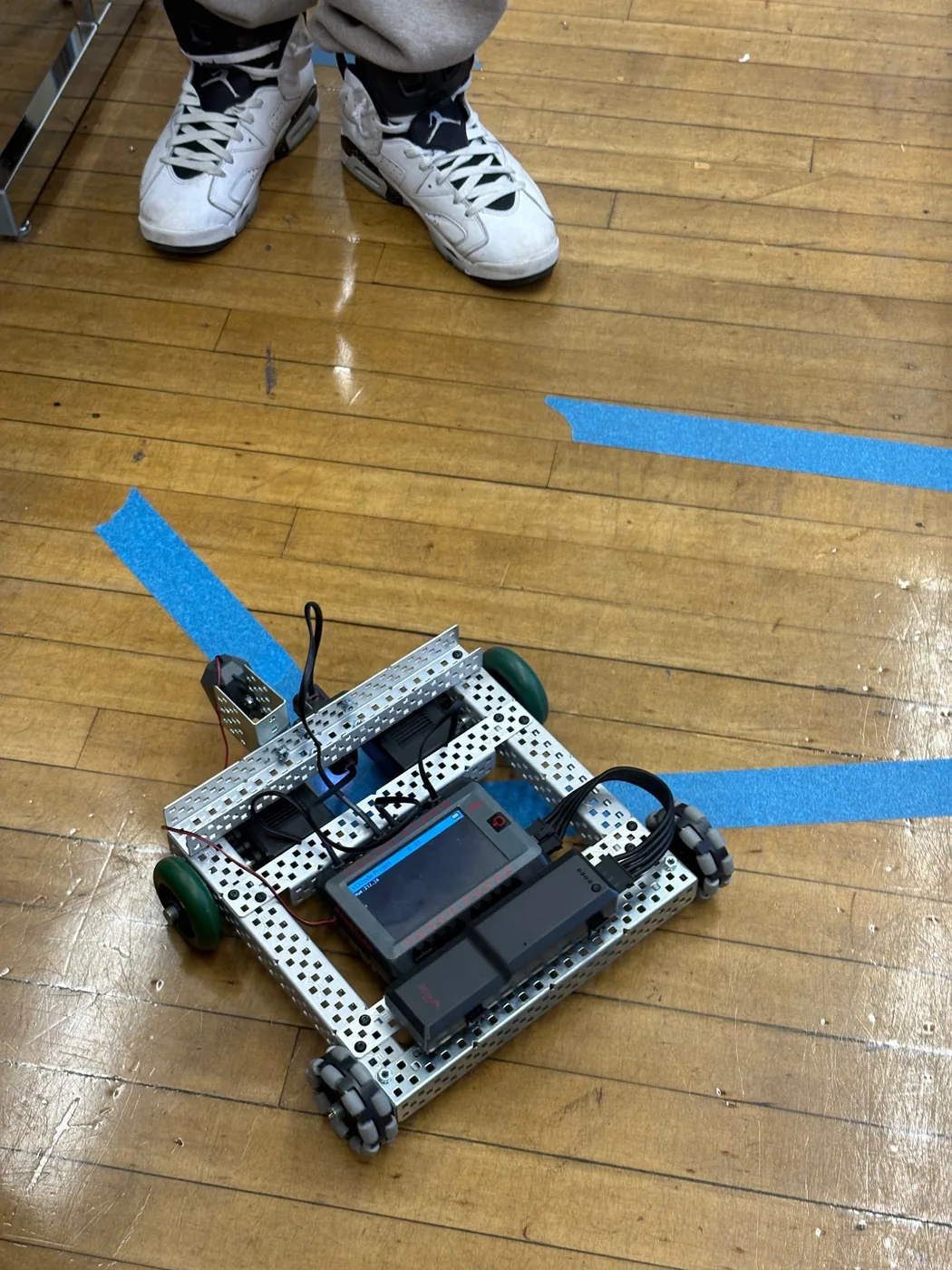 FIG. 04 / LINE TRIAL
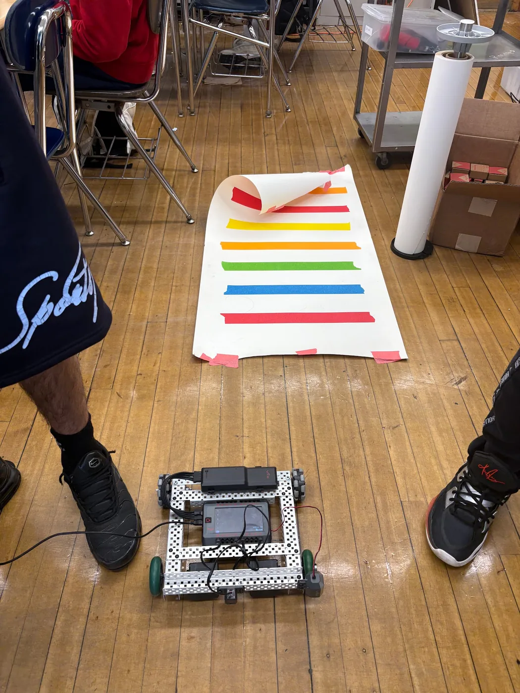 FIG. 05 / COLOR TEST
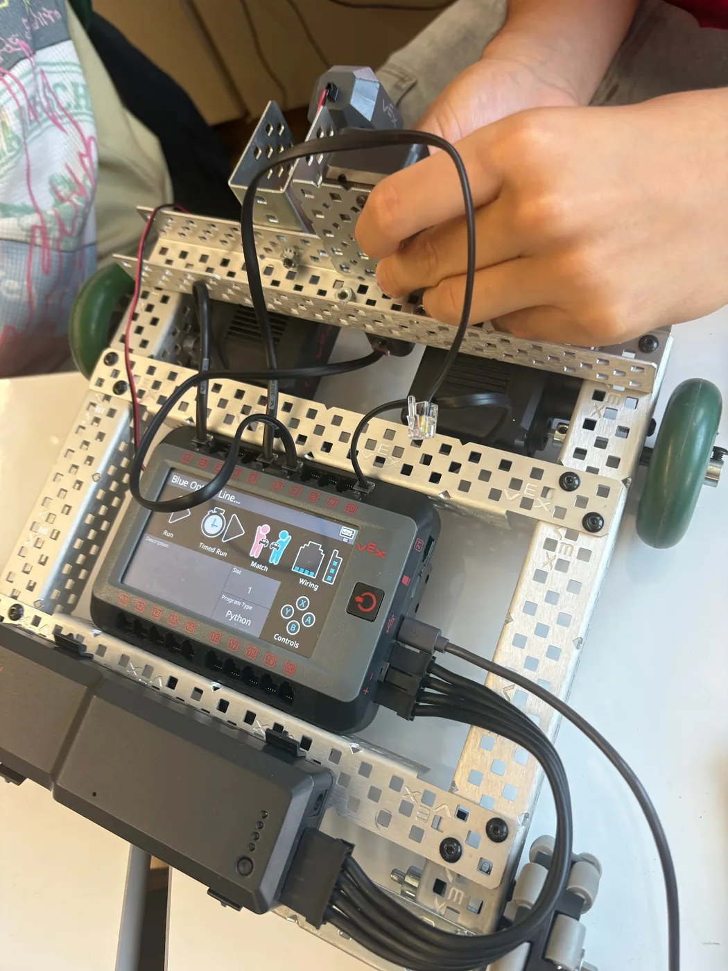 FIG. 06 / SENSOR MOUNT
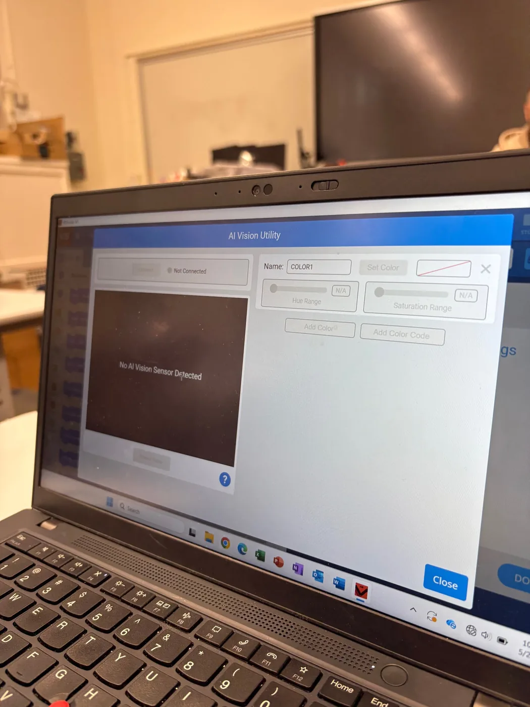 FIG. 07 / CONFIGURATION
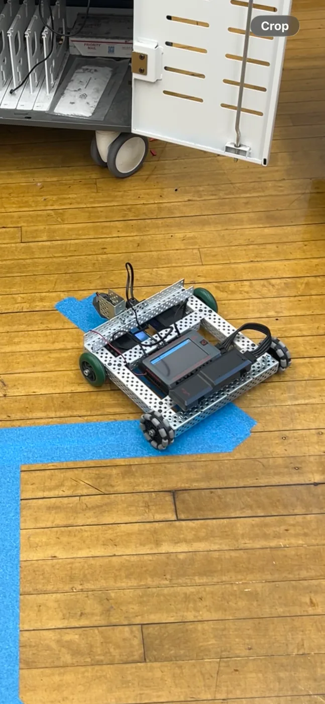 FIG. 08 / COLOR REFERENCE
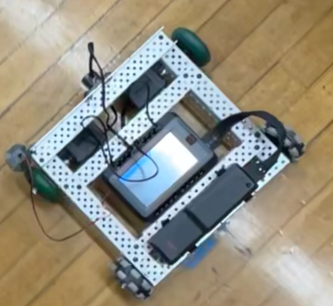 FIG. 09 / HARDWARE DETAIL
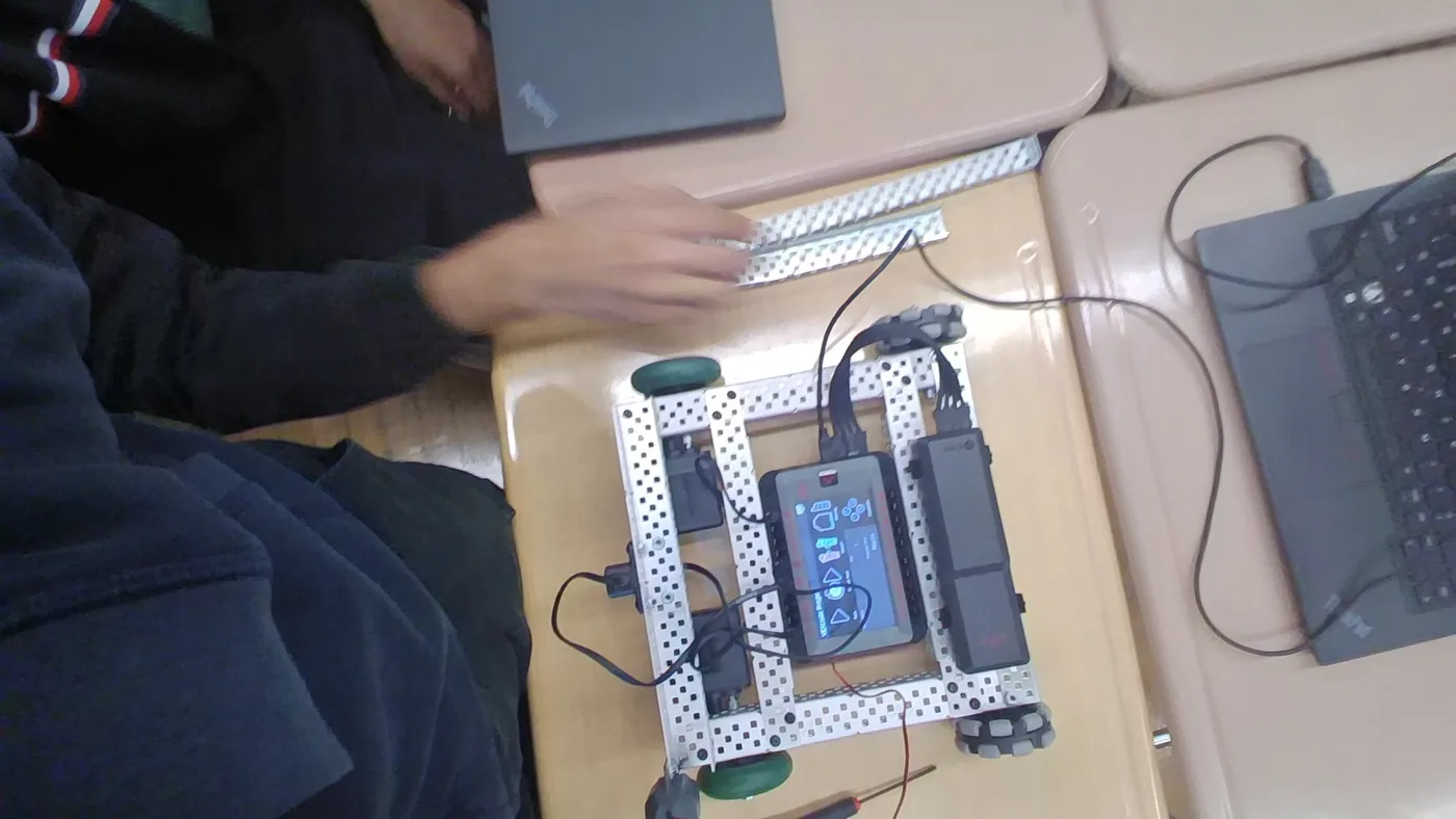 FIG. 10 / CODE + HARDWARE
07 / NEXT SENSOR LAYER
The final project entries document a new AI Vision sensor being attached, configured, and made visible on the computer. The first display attempt worked on the V5 brain but not on the laptop; I resolved the configuration so the view appeared on the computer by May 22.
The notes stop at the setup stage. They do not show the AI Vision sensor controlling the line-following robot yet, so the next engineering step would be to define an object-detection task and integrate its output into a tested control loop.
08 / ENGINEERING × FINANCE
This project did not include a budget or cost analysis. The connection to finance is a reflection on what makes a design practical to build and maintain.
Even a small robotic car depends on resources: a brain, motors, a sensor, a battery, structural parts, wiring, and time for assembly and testing. When a wheel binds or a cable fails, the cost is not only the replacement part. It can also be the time spent diagnosing the symptom and repeating a test.
The code changes also have a resource tradeoff. A simpler controller is easier to inspect and tune, while stronger recovery behavior can help the robot continue after losing the line but adds more conditions to debug. The useful design is the one whose added complexity improves performance enough to justify the extra setup and maintenance.
I did not record kit prices, labor hours, or failure rates, so I cannot calculate a true unit cost or return. A future version could log time spent on each iteration, count successful runs out of a fixed number of trials, and compare the simplest working controller with the more advanced search routine.
Conceptual framework · project costs were not recorded