Component types
Wheel · stack · linkage arm · body · cow catcher
 Aiden YeungENGINEERING × FINANCE
MAIN SOPHOMORE-YEAR PROJECT / GRADE 10
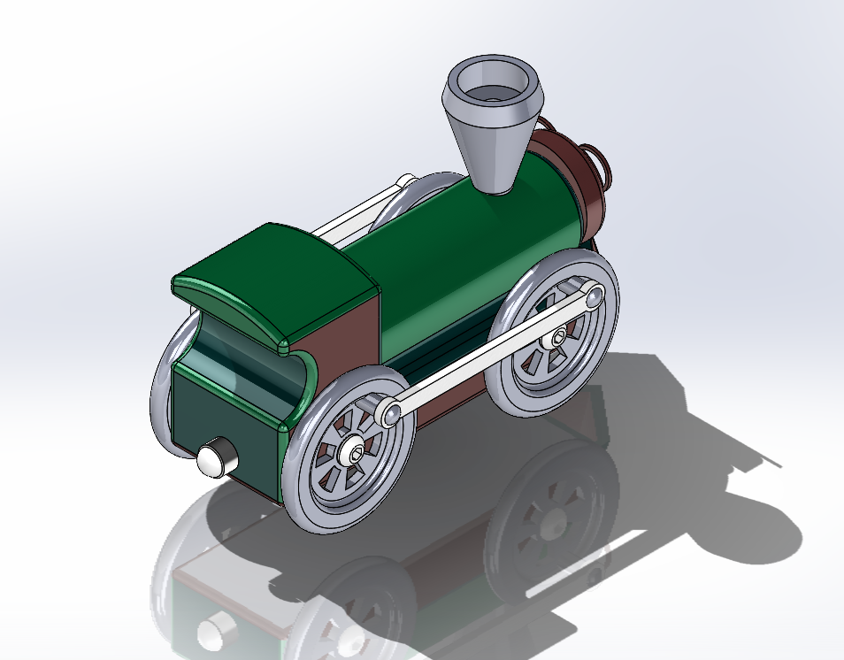
A toy locomotive modeled one component at a time, then assembled in SolidWorks to review fit, alignment, and motion. The project moves from dimensioned sketches to a complete digital train and assembly animation.
A TOOL FOR THINKING IN 3D
SolidWorks is a computer-aided design (CAD) program used to create precise 3D parts and combine them into assemblies. In this project, it provided a way to shape each train component, inspect the geometry from different views, and check how the parts fit together digitally.
CAD turns a design idea into a model that can be inspected and revised before anything is made. The train project uses that workflow to connect sketches, individual components, and one assembled locomotive.
01 / DESIGN INTENT
The original project focused on modeling the train's pieces and assembling them in virtual space to see how they fit and move together.
Design question How can independently modeled details read as one coherent locomotive and move together in the assembly?
02 / COMPONENT BREAKDOWN
Each component has a distinct role in the model. The cards use the original SolidWorks renders and descriptions.
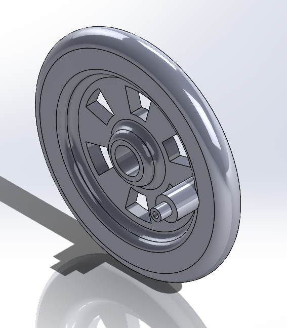
Role: The wheel guides the train along the rails and enables rolling movement. Design reading: Its circular profile and hub define the connection point; the spoke pattern adds detail while keeping the wheel visually legible.
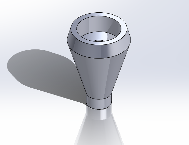
Role: Represents the exhaust stack associated with steam and smoke. Design reading: The tapered profile and open rim make it read as a distinct upper feature and give the locomotive a recognizable silhouette.
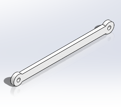
Role: The project identifies this arm as the connection coordinating wheel movement. Design reading: The elongated bar and end holes suggest a pivot connection at each wheel, making alignment and joint placement central to the assembly.
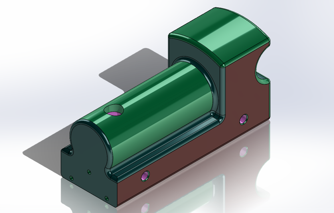
Role: Forms the central structure that visually organizes the locomotive and provides locations for the other modeled elements. Design reading: The profile and face sketches show how the main volume and openings were shaped before assembly.
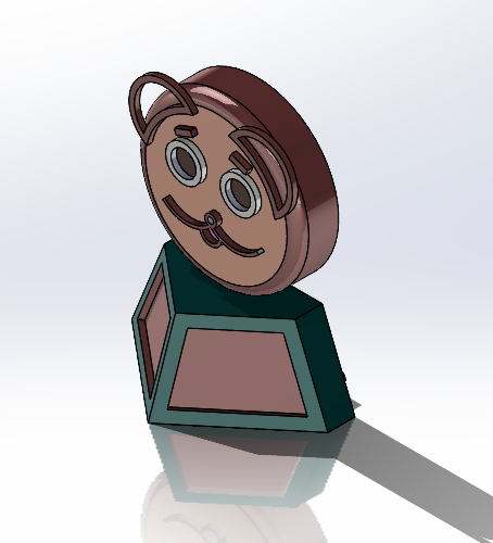
Role: Creates the locomotive's distinct front-end detail. Design reading: Its face sketch uses aligned, dimensioned shapes to build the character-like features; the separate isometric study documents the form before extrusion.
03 / FORM STUDIES
Rendered and sketch views reveal how the locomotive body and front detail were developed. These are the original project images, not recreated mockups.
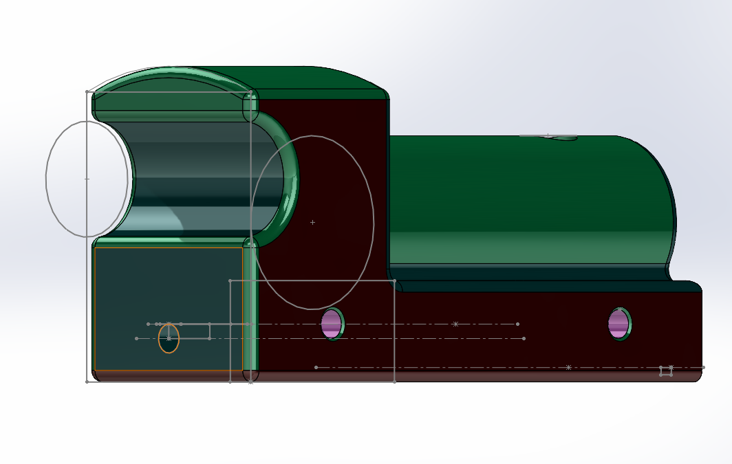 BODY / PROFILE
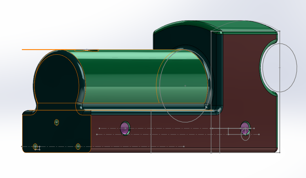 BODY / ELEVATION
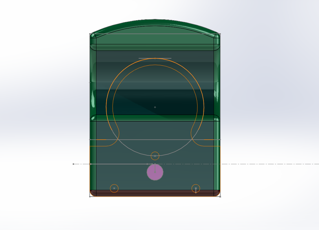 BODY / FACE
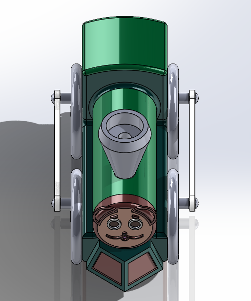 ASSEMBLY / FRONT
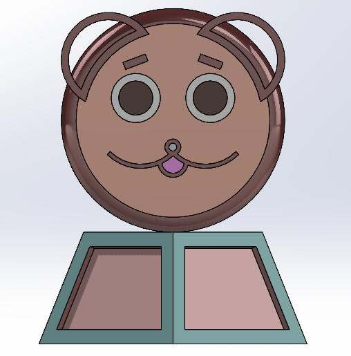 COW CATCHER / FACE
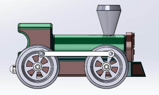 ASSEMBLY / SIDE
04 / SKETCH TO GEOMETRY
The original documentation shows the cow catcher before extrusion and a dimensioned face sketch used to align its details.
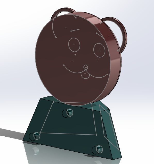 FIG. 03A
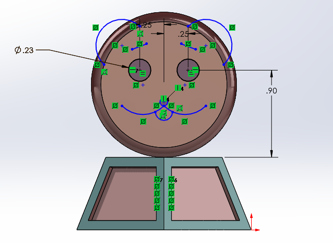 FIG. 03B
05 / ASSEMBLY MOTION
SolidWorks assembly tools let the parts be viewed together. The animation documents the model moving as a system; it is a digital preview, not a physical track test.
06 / ENGINEERING × FINANCE
This is a finance reflection on the model—not a cost analysis performed during the project.
CAD makes a design concrete enough to discuss in terms of resources. A parts list can lead to questions about materials, manufacturing steps, assembly time, and how much of each component a product needs.
Those choices affect both up-front investment and cost per unit. More parts or more complex geometry may mean more operations and assembly work; simplifying or standardizing components can change the economics, especially as production volume grows.
This train project did not include a bill of materials, supplier quotes, budget, or production run. Looking at it through finance helps me see the next questions to ask: what would it cost to make, how many could be produced, and would the product justify the resources invested?
Conceptual next step · no project cost data recorded
07 / PROJECT RECORD
The project brings together distinct CAD components, sketch details, an assembled view, and a motion preview.
Wheel · stack · linkage arm · body · cow catcher
Parts brought together in SolidWorks for a fit and motion review.
A short animation documents the locomotive model in movement.
Digital CAD model and assembly animation. The source documentation does not show a physical prototype or measured operating results.