
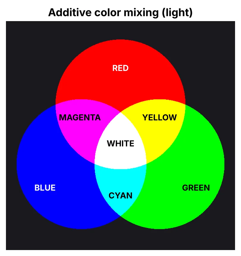
First channel in the additive color mix.
SENIOR-YEAR PROJECT / GRADE 12 / NOVEMBER 4, 2026
Arduino
RGB Light
I used an Arduino Uno to control a common-cathode RGB LED, first cycling its red, green, and blue channels, then combining those channels to create mixed colors. The activity connected circuit fundamentals to code, PWM brightness, physical controls, and a serial interface.
YEARSenior · Grade 12
PLATFORMArduino Uno
OUTPUTCommon-cathode RGB LED
CONTROLPWM · analogWrite()
INPUT EXTENSION3 potentiometers · Serial
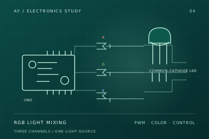 FIG. 01 / THREE CHANNELS, ONE LIGHT
Design question How can three independent LED channels be controlled and mixed to create a repeatable, user-adjustable color?
NOV 2026 · PERIOD 601 / THE IDEA
One LED package.
Three light sources.
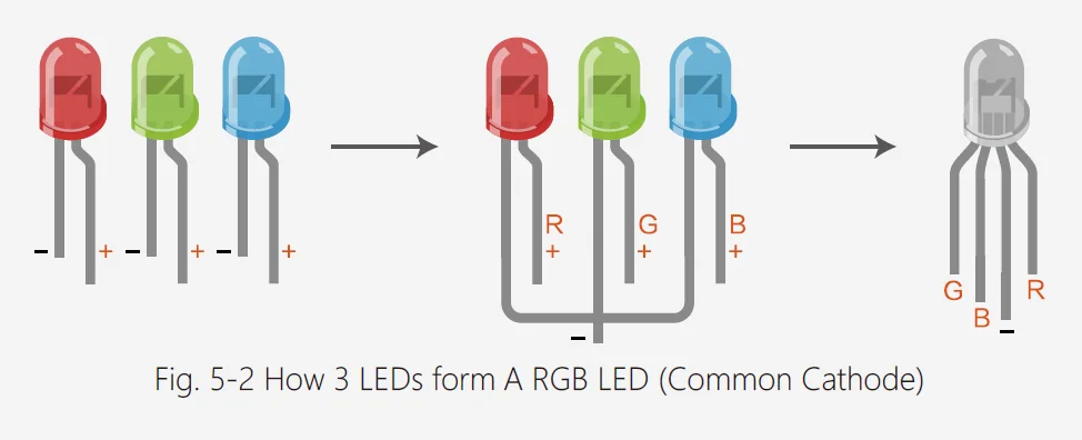
An RGB LED combines red, green, and blue emitters inside one component. Treating each emitter as a separate output turns the LED into a small color-mixing system.
Second channel; its perceived brightness can differ from red and blue.
Third channel, mixed with the other two as light.
Vary the three channel values to create a range of colors, from black/off to combined white light.
↳
My analysis This project sits between electronics and visual design. The circuit controls electrical current, while the viewer experiences hue and brightness. A value like (255, 60, 0) is a digital instruction; the color it appears to be still depends on the LED, its current-limiting resistor, viewing conditions, and human perception.
02 / CIRCUIT ARCHITECTURE
Three protected outputs
share one ground.
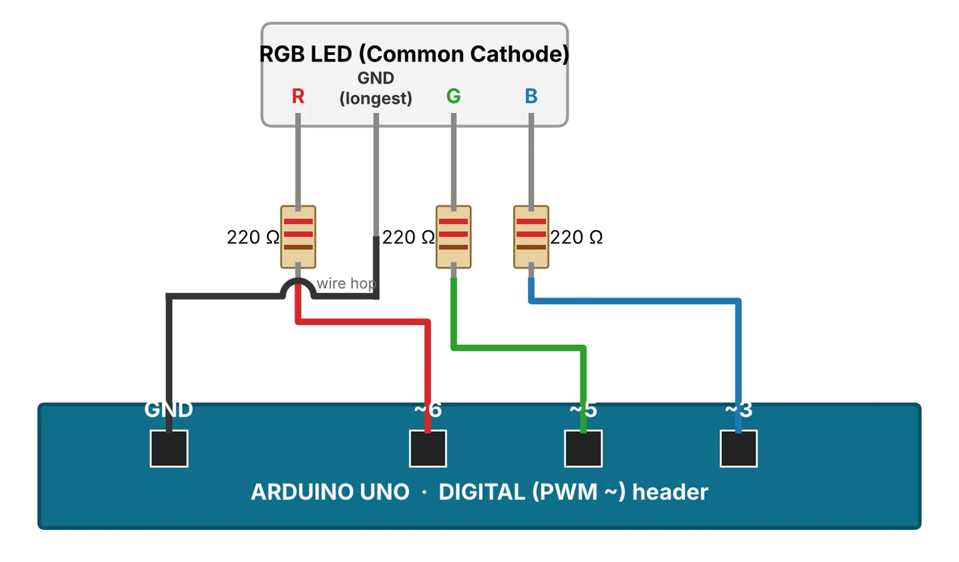
The common cathode connects to ground. Each color anode gets its own resistor and its own PWM pin, so each channel can be controlled independently.
Common cathode → GND
The activity uses a common-cathode LED. Its longest leg is the shared negative connection, which returns current to the Arduino ground.
One 220 Ω resistor per color
Each color channel receives its own series resistor. This limits current through that emitter and keeps the three channels from sharing one uncontrolled current path.
Pins 6, 5, and 3
These Uno pins support PWM. The sketch maps red to D6, green to D5, and blue to D3, matching the activity’s wiring table.
Breadboard + jumpers
The breadboard keeps LED legs and resistor connections separated into rows; jumper wires carry each channel and the shared ground to the board.
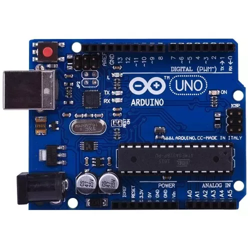
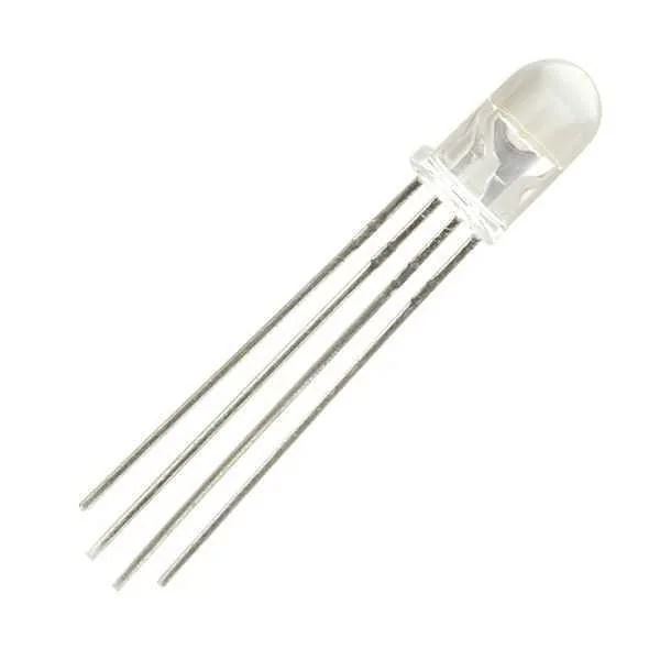
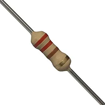
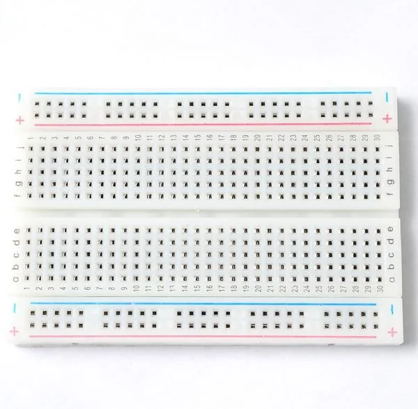
Build note The supplied activity says to unplug USB power while wiring and check every connection before reconnecting. It also notes that a common-anode LED behaves in reverse, so confirming the LED type matters before interpreting the code.
03 / PWM + CODE
Brightness becomes
a number.
The Uno’s digital pin is either on or off. PWM switches it quickly, and the duty cycle controls the average brightness perceived by the eye.
ONE CHANNEL / THREE DUTY CYCLESanalogWrite(pin, value)
\n 0 = 0% duty cycle127 ≈ 50% duty cycle255 = 100% duty cycle
\n BASE PROGRAM / RGB_LEDTHREE COLOR STATES
The starter loop turns on one channel at a time. The documented timing gives red one second, then green and blue half a second each.
const int redPin = 6;
const int greenPin = 5;
const int bluePin = 3;

void setup() {
  pinMode(redPin, OUTPUT);
  pinMode(greenPin, OUTPUT);
  pinMode(bluePin, OUTPUT);
}

void loop() {
  analogWrite(redPin, 255);
  analogWrite(greenPin, 0);
  analogWrite(bluePin, 0);
  delay(1000);

  analogWrite(redPin, 0);
  analogWrite(greenPin, 255);
  analogWrite(bluePin, 0);
  delay(500);
}
The blue state follows with its own channel at 255; then the loop begins again.
WHY THE FUNCTION MATTERS
One call represents one color.
The rainbow challenge introduces setColor(r, g, b). That function keeps the three channel writes together, so the main loop can express a color as one RGB tuple instead of repeating the same low-level wiring logic every time.
REDORANGEYELLOWGREENBLUEPURPLEWHITEOFF
Eight states × one second each = an eight-second programmed cycle.
04 / EXPERIMENTS + OBSERVATIONS
From named colors
to RGB coordinates.
A color name is a human label. The Arduino needs three channel values, each from 0 to 255, to produce that color on the LED.
| Color | Red | Green | Blue | Interpretation |
|---|---|---|---|---|
| Yellow | 255 | 255 | 0 | Red + green light |
| Magenta | 255 | 0 | 255 | Red + blue light |
| White | 255 | 255 | 255 | All three channels |
| Orange / mix task | 255 | 60 | 0 | Lower green level |
| Orange / rainbow code | 255 | 127 | 0 | Starting point, then tune by eye |
RGB values are not paint recipes
Adding red and green light makes yellow; adding all three channels makes white. This is additive color mixing, so increasing one channel changes the emitted light rather than mixing pigment.
Code values need visual calibration
The activity records two green levels for orange in separate exercises: 60 in the color table and 127 in the rainbow sequence. The guide explicitly recommends tuning by eye because a physical LED does not match a monitor. This makes calibration part of the engineering work.
Channel balance affects the result
Equal numeric values do not guarantee equal perceived brightness across red, green, and blue. A more refined version could measure the output under fixed conditions and create a correction table for more consistent colors.
THE REPRESENTATION
(R, G, B)→(255, 60, 0)→LED APPEARS ORANGE
Digital command → channel output → perceived color.
05 / HUMAN INPUT
Turn the color mix
into an interface.
The color dial challenge adds three potentiometers. A person supplies the RGB values by turning knobs instead of editing the sketch for every color.
KNOB INPUTanalogRead()0–1023
÷ 4CHANNEL VALUEanalogWrite()0–255
→LIGHT OUTPUTRGB LEDMixed color
Each potentiometer’s wiper connects to an analog input: red to A0, green to A1, and blue to A2. The program divides each 10-bit reading by four to fit PWM’s 8-bit output range, then prints the resulting R, G, and B values to the Serial Monitor at 9600 baud. A short 50 ms loop delay keeps the stream and color updates at a practical pace.
COLOR DIAL / DATA FLOW
int rIn = analogRead(A0);
int gIn = analogRead(A1);
int bIn = analogRead(A2);

int r = rIn / 4;
int g = gIn / 4;
int b = bIn / 4;

setColor(r, g, b);
Serial.print("R: ");
Serial.print(r);
Serial.print("\tG: ");
Serial.print(g);
Serial.print("\tB: ");
Serial.println(b);↳
What changed The project moves from a fixed sequence to a live control surface. The potentiometers expose the three inputs directly; the Serial Monitor makes those settings observable. That loop connects physical interaction, numeric data, and the color the LED produces.
06 / EXTENSIONS
Scale up the palette
without losing control.
The activity adds three ways to extend the basic circuit: cycle through presets, sweep a grid of combinations, or accept values from a person.
Preset color cycle
The documented sequence runs red, orange, yellow, green, blue, purple, white, and off. A helper function writes the three channels for each state; one-second delays create a steady visual rhythm.
Potentiometer inputs
Three 10 kΩ potentiometers adjust the three color channels. This changes the circuit from a passive output into a physical interface for exploring mixed colors continuously.
Type a color
The activity’s serial-input extension asks for red, green, and blue values, constrains them to the valid range, shows the color for five seconds, and then turns it off.
HOW MANY COLORS?
Resolution creates a computation tradeoff.
At 6 selected levels per channel—0, 51, 102, 153, 204, and 255—a nested sweep covers 6 × 6 × 6 = 216 combinations. Testing every possible 8-bit value would require 256³, or 16,777,216 combinations. At 50 ms per color, that is about 9.7 days of display time before loop overhead.
R×G×B6³ = 216
This is where sampling matters: use larger steps for a fast overview, then finer steps around the colors worth tuning.
07 / HARDWARE DEMONSTRATIONS
The code becomes
visible light.
These short clips show the physical Arduino and LED behavior that accompanies the circuit and code activity.
DEMO / 01
DEMO / 02
08 / ENGINEERING × FINANCE
Compact parts list.
High-value iteration.
No project budget or component prices were recorded, so this is a cost-structure analysis rather than a claimed savings calculation.
The bill of materials is compact: one Uno, one RGB LED, three current-limiting resistors, a breadboard, jumper wires, and—when using the color dial—three potentiometers. A shared controller and one LED package provide many output colors without needing a separate lamp for each hue.
The more important economic question is how quickly a design can be adjusted and tested. A software change can alter a color preset at little material cost; a wiring error or missing resistor can still consume setup time or damage a component. Clear pin labels, one resistor per channel, reusable functions, and a simple wiring map reduce avoidable rework.
For a product version, I would compare the cost and usability of three physical knobs with a serial or screen-based color picker, then test color consistency across LEDs. The better design depends on whether the goal is a low-part-count demonstration, a hands-on controller, or accurate repeatable color output.
DESIGN CHOICES → PRODUCT QUESTIONS
PARTS +
ASSEMBLYCONTROL
METHODCALIBRATION
TIMEUSER
EXPERIENCE
ASSEMBLYCONTROL
METHODCALIBRATION
TIMEUSER
EXPERIENCE
Conceptual model · prices and labor were not measured